| |
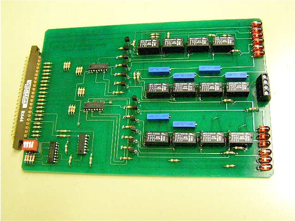 |
The result was a custom board
solution that provides a broad range of temperatures and superior resolution. These are
commanded with discrete Ethernet I/O.
Additionally, we developed multichannel thermocouple sourcing cards that are capable of
simulating both J & K type thermocouples. These included sample and hold circuitry to
allow for a few of our analog signals to control multiple T/C channels.
|
|
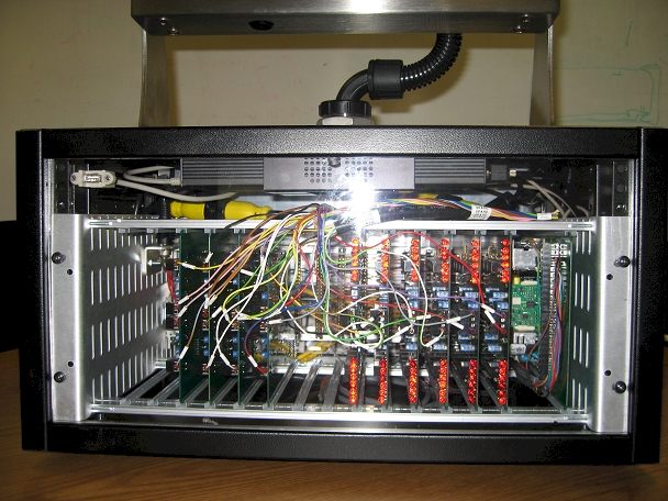
| All of these boards are housed in a removable
rack, which itself is housed in a convenient cabinet that is equipped with a Stealth
industrial PC and 17” Touchscreen. |
 |
|
 |
|
|
Screens and Programming
The system can operate both in a manual mode - in which signals are commanded through
screen input as needed - or in completely automatic mode in which the sequence of
operation is commanded through a recipe system. In addition to the time savings of
automatic testing and saving of data, the system also streamlines your process by allowing
for repeated use of recipes once the first one has been set up. We will first detail the
control screens and show how they can be used for manual simulation and then show how the
system is set up for automatic operation.Temperature
Simulation:
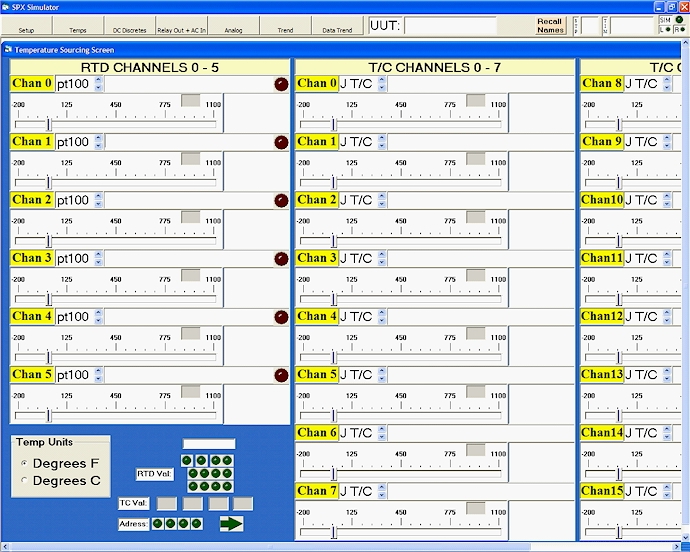
Below is a screenshot of the Temperature Simulation Screen. There are (6) RTD channels
that are freely selectable as pt100 or pt1000 type. You can name each of the channels for
keeping track of them and also populating the trend screens. Settings can be made either
by the slider bar or directly entering the desired temperature output equivalent
resistance. The program performs a lookup of data from NIST standards whenever any change
is made. You can work in either degrees C or F.
To the right there are (16) thermocouple channels that are similarly laid out to the RTD
channels. Here you select J or K type and enter a name and make adjustments with the
slider or direct entry just like the RTD channels. |
 |
|
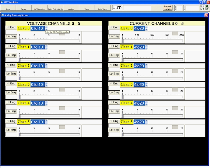
Analog Simulation:
Below is a screenshot of the Analog Simulation Screen. There are (6) Voltage channels and
(6) Current channels. To use the voltage channels, first select one of the various voltage
types (-10 to 10, 0 to 10, 0 to 5, 1 to 5V). Then, you can enter high and low engineering
units that will rescale the slider bar limits and allow you to work in these units instead
of the raw units, if desired. Do the same for the current channels, where raw units are 4
to 20, or 0 to 20mA. |
 |
|
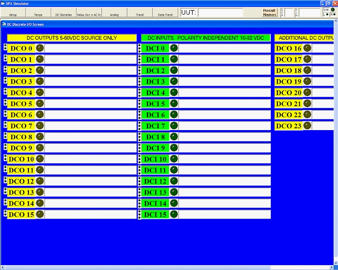
Discrete Simulation:
Here is the DC discrete simulation screen. Simply click or touch the output indicators to
change state. Output power must be sourced from the Unit-Under-Test and can be from 5 to
60VDC. Inputs are polarity insensitive. Use the text fields to name your channels. Naming
them also populates the trend chart (shown later). |
 |
|
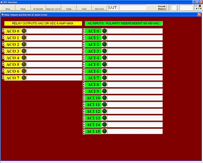
| The AC discrete screen operates similarly.
The outputs are relay and the inputs are also polarity insensitive. |
 |
|
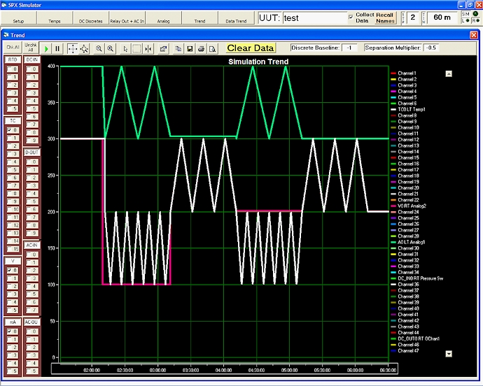
Real Time Trend Screen:
This is the Real-Time Trend Screen. It is useful as a historical log of what happened
during simulation. In addition to plotting the simulation outputs, it will also log the
outputs from the Unit-Under-Test if they are wired to inputs of the simulation system. The
trend is scalable in every way and you can select which channels to see with the check
boxes on the left. You can also pan the trend in all directions. |
 |
|
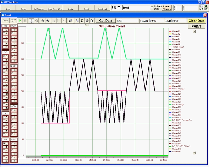
Historical Trend Screen:
This is the Historical Trend Screen. Here you can recall data from disk for a date range
that is specified from a virtual calendar. You can also retrieve data by serial number. As
with the real time trend, you can select which channels to see - particularly useful if
the trend gets busy. Again, the trend is scalable and pan-able in every way. |
 |
|
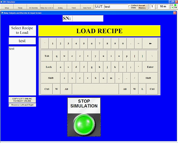
Recipe System - Recipe Select Screen:
Here is the Recipe Screen where you can select from pre-programmed recipes. Recipes are
built in convenient MSAccess forms shown later. As you type in a recipe name, similar
items appear in the list-box. Just make a selection and click or touch the Start
Simulation button. The system will automatically populate the values in the above screens
as defined by the recipe forms that I will detail below. |
 |
|
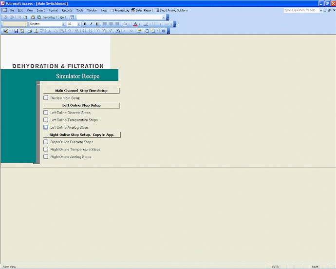
Recipe System - Recipe Entry
Database:
This is the main switchboard for the recipe database. Form links are laid out for step by
step entry. Just click or touch to open the forms. You populate the forms in such a way
that will exercise your Unit-Under-Test as needed. Being able to automatically perform
tests and collect the data is one big advantage of this system, while another is only
having to set up a recipe once for a particular type of unit to test.
(Our customer’s logo is covered up) |
 |
|
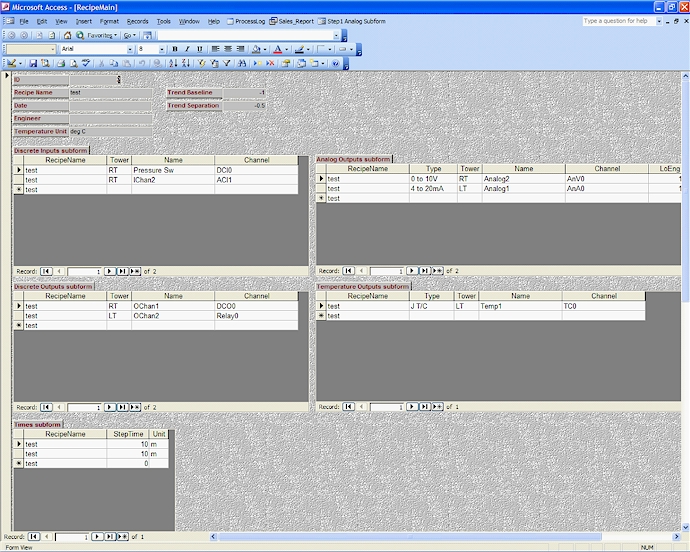
| This is the main recipe setup form where you
can setup the channel names and define physical channels of the simulator to suit your
particular test. Do this for all the output types as needed - RTD, T/C, discrete - and
also the discrete inputs to the simulator, if desired. For this customer, the process to
be tested is defined in steps, so here you can define the step duration as well. |
 |
|
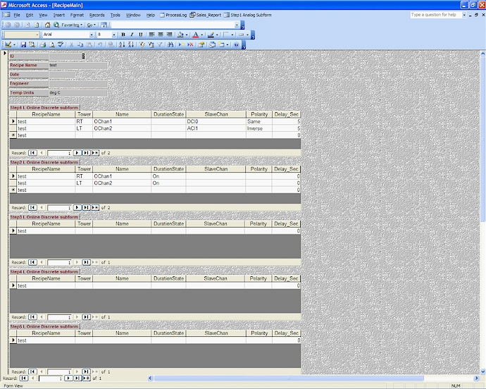
| This is the Discrete Steps form. Here you can
setup functionality for discrete simulation outputs for each step. The name is selectable
by drop-down list of the items that were entered in the main form that defines the
channels. You can set outputs to be on or off for the duration of the step, or slave the
output off of some other input (output from UUT) as same polarity or inverse and give a
delay. You only have to setup channels that need to change during a step to exercise your
UUT as needed. |
 |
|
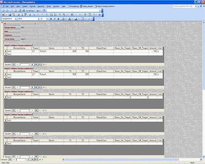
| This is the Temperature Steps form. Here you
can setup functionality for temperature simulation outputs for each step. The name is
selectable by drop-down list of the items that were entered in the main form that defines
the channels. You can define units to be C or F and set two temperatures to oscillate
between at a time interval or select a slave channel from a drop down list of inputs and
outputs and give an On Target and Off target to attain at defined Interval. You only have
to setup channels that need to change during a step to exercise your UUT as needed. |
 |
|
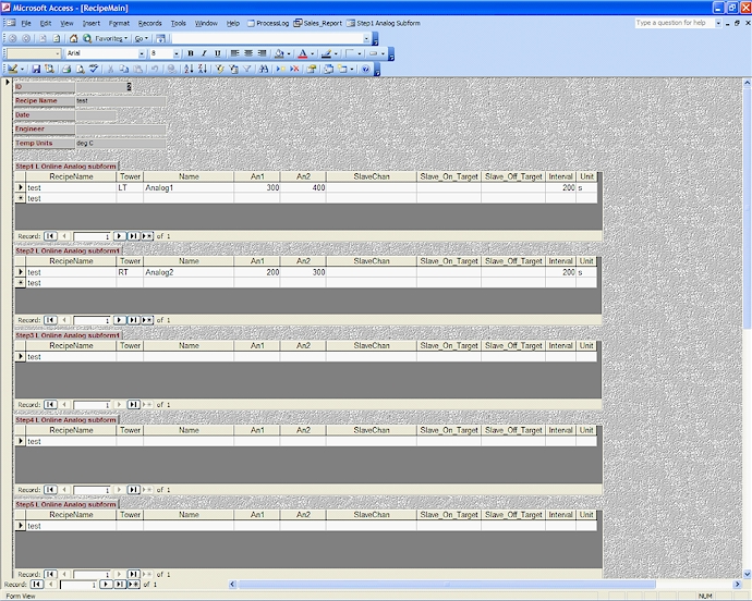
| This is the Analog Steps form. Here you can
setup functionality for Analog simulation outputs for each step. The name is selectable by
drop-down list of the items that were entered in the main form that defines the channels.
You can set two Analog values to oscillate between at a time interval or select a slave
channel from a drop down list of inputs and outputs and give an On Target and Off target
to attain at defined Interval. You only have to setup channels that need to change during
a step to exercise your UUT as needed. |
 |
|
If you have read this far, thank you for your
interest in our extremely complete and competent simulation system. While it is somewhat
customized for the particular customer, any variation is possible. We are confident that
this system will provide you with huge time savings for your engineering, quality and
technical personnel that are involved with testing as it can test your machine or process
automatically and also will prevent costs from returns or field service due to the ease of
use and completeness of testing possible.
Please consider Brown Controls and Integration for your simulation needs. |
|